We have collected lots of pictures with any luck this picture serves for you and also help you in locating the response you are searching for.
Chromalox heater wiring diagram.
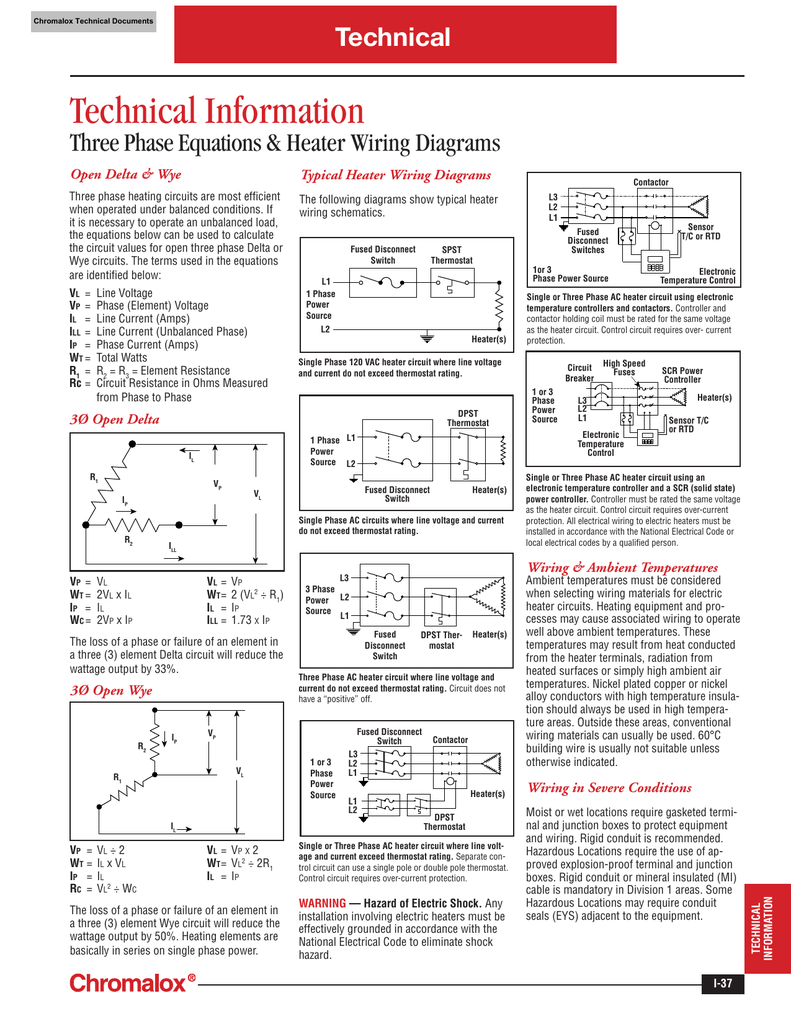
Typical heater wiring diagrams the following diagrams show typical heater wiring schematics.
Intellitrace modbus wiring registry map instructions.
Single phase ac circuits where line voltage and current do not exceed thermostat rating.
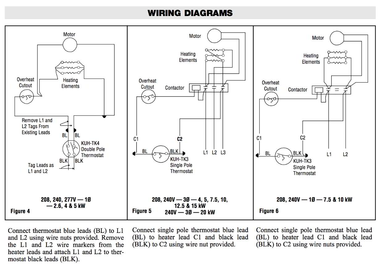
Refer to appropriate wiring diagram for your model heater from the wiring guide on next two pages.
Assortment of chromalox immersion heater wiring diagram.
Collection of chromalox heater wiring diagram.
Circuit does not have a positive off.
It shows the components of the circuit as simplified forms and also the power and signal links in between the gadgets.
Either 120 208 or 240 volt single phase since heater circuit could be 480 volts single or three phase.
Chromalox 100 years.
A wiring diagram is a streamlined conventional photographic depiction of an electrical circuit.
A wiring diagram is a simplified standard photographic depiction of an electric circuit.
Use wiring suitable for the anticipated operating temperatures.
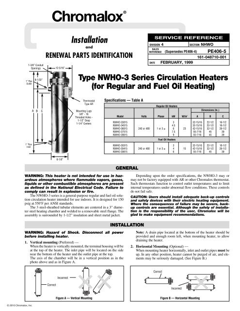
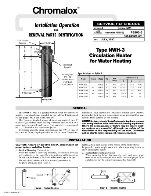
Circulation heaters oil heaters.
If high humidity is encountered the con duit should slope down away from the heater.
Heaters are not provided with a control switch and should be.
It reveals the elements of the circuit as streamlined shapes and the power and signal links between the gadgets.
Sleeving or insulated tubing is recommended.
Unless the heater is specifi cally marked for use with low.
Thermocouple wiring clear of heater terminals to prevent accidental short circuits.
Circulation heaters corrosive solutions and high temperature gas.
If an external transformer is used to step down the voltage for oper ating the fan motor use appropriate wiring diagram figures 3 5 or 7.
Chromalox wiring practices for electric heaters.
Chromalox thermostat kits hvh tk6 and hvh tk6 for field installation only in chromalox hvh 02 through hvh 15 heaters.
Circulation heaters for oil or water heating installation manual pe414 nwho.
Chromalox heat flo thermostat kit wiring diagram 1 of 2 for chromalox heatflo type kuh tk3 and kuh tk4 used only in kuh 02 through kuh 45 heaters.